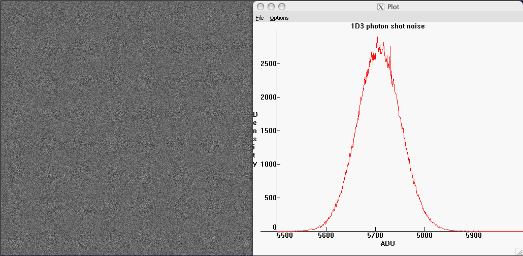
Fig.1 - Photon shot noise in an image of the sky from a Canon 1D3 (in the green channel). In the histogram at right, the horizontal coordinate is the raw level (raw units are sometimes called analog-to-digital units ADU or data numbers DN), the vertical axis plots the number of pixels in the sample having that raw level. The photon noise was isolated by taking the difference of two successive images; the raw values for any one pixel then differ only by the fluctuations in the photon count due to Poisson statistics (apart from a much smaller contribution from read noise).
The noise histogram is essentially a Gaussian distribution -- a standard "bell curve". The standard deviation of this bell curve is the width of the bell. Fluctuations in photon counts from pixel to pixel are completely uncorrelated; in terms of its spatial variation, photon shot noise is white noise (in other words, it has equal strength at all spatial frequencies); this means that it has a uniform salt-and-pepper appearance with no structure or pattern.
An important characteristic of fluctuations obeying Poisson statistics is that their standard deviation -- the typical fluctuation away from the average in the typical count -- is equal to the square root of the average count itself. That is, if 10000 photons are collected on average, the typical fluctuation away from this average number of photons will be about 100 -- the counts will typically range from about 9900 to 10100. If instead on average 100 photons are collected, the variation from count to count will be +/- 10. Thus, as the signal grows, the photon shot noise also grows, but more slowly; and the signal-to-noise ratio increases as the square root of the number of photons collected. The higher the illumination, the less apparent the shot noise; the lower the illumination, the more apparent it is.
In an ideal world, the digital number recorded in the raw data would be directly proportional to the photon count. The constant of proportionality between the number of photons and the corresponding raw value is conventionally and somewhat inaptly called the gain of the sensor (it is not really a gain, rather it is a conversion factor between photo-electron counts and raw values). Since each doubling of ISO doubles the raw value for a given exposure, the gain is inversely proportional to ISO -- doubling the ISO cuts the gain in half, because the same number of photons captured are converted to a raw value twice as big when the ISO is doubled.
In the real world, the raw level does not precisely reflect the photon count. Each electronic circuit component in the signal processing chain -- from sensel readout, to ISO gain, to digitization -- suffers voltage fluctuations that contribute to a deviation of the raw value from the ideal value proportional to the photon count. The fluctuations in the raw value due to the signal processing electronics constitute the read noise of the sensor.
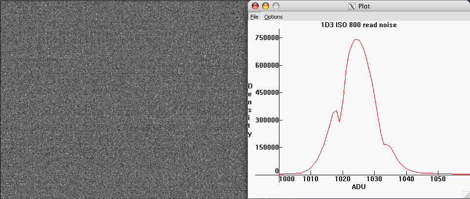
Fig.2 - Read noise of a 1D3 at ISO 800.
The histogram of the noise is approximately gaussian.
The average value
of 1024 is due to an offset Canon applies to raw data
(see page 2).
The read noise can be isolated by taking a "black frame" image, an exposure with the lens cap on and the highest available shutter speed; there are thus no photons captured, and only the electronic noise from reading the sensor remains.
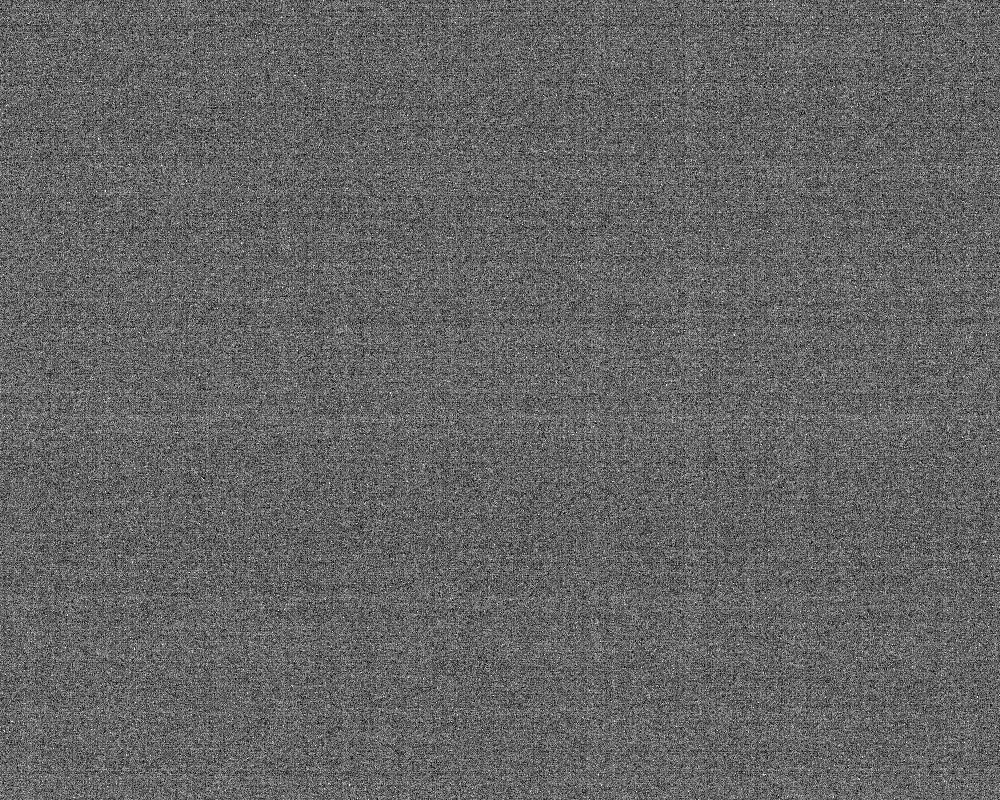
Fig.3 - Pattern noise in a 20D at ISO 800
(1000x800 pixel crop).
Fixed pattern noise can be removed. By making a template from the average
of 16 identical blackframes and subtracting it from the image
most of the fixed pattern noise is removed. The result may be seen
by mousing over the image.
The residual variable component of pattern noise
consists in this example largely of horizontal banding noise.
Pattern noise can have both a fixed component that does not vary from image to image; as well as a variable component that, while not random from pixel to pixel, is not the same from image to image. Figure 3 shows the read noise of a 20D at ISO 800 (a 1/1000sec exposure with the lens cap on, with a levels adjustment made for visualization purposes). There is both horizontal and vertical banding present. A template for fixed pattern noise was created by averaging sixteen identical blackframes; this has the effect of averaging out any variable, fluctuating component of read noise, leaving mostly the fixed component. The effect of subtracting the fixed pattern noise template from the read noise may be seen by mousing over the image in figure 3. Vertical banding largely disappears in this example, leaving some variable banding noise in the horizontal direction, as well as a homogeneous (white) component of read noise; the width of the read noise histogram decreases by about 20%. This gives an indication of how visually disruptive pattern noise can be -- even though the fixed pattern noise is only about 20% of the overall noise, it is quite apparent because our perception is adapted to picking out patterns, finding edges, etc.
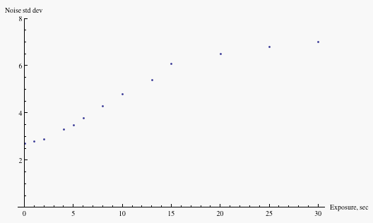
Fig.4 - Thermal noise in 20D blackframes at ISO 400.
The knee in the data at exposure time 15sec is due to the max pixel raw level
reaching 4095
(the maximum possible value on this camera),
indicating that the rise in standard deviation is largely
due to a few outlyers in the distribution.
The noise level rises as a function of exposure time, with the slope decreasing above an exposure time of about 15sec in this particular sample. The cause of this change in behavior is that the rise in the standard deviation is largely due to a few "hot" pixels out on the tail of the distribution; when the raw values of these pixels reach 4095 (the maximum possible value for this camera), their contribution to the standard deviation saturates, and only the other pixels contribute to a (slower) rise in the standard deviation. In crops from the same image used to generate the above plot, but chosen to avoid such "hot" pixels, the standard deviation rises much more slowly.
To show the growth in number of these outlying "hot" pixels, Figure 5 plots in white the pixels whose values are four or more standard deviations above the mean (in a quadrant of the crop used to generate Figure 4) for two different exposure times.

Fig.5 - Hot pixels are the main contributors
to thermal noise. Shown in white are the pixels whose values are four or more
standard deviations above the mean. On the left, exposure time is 15sec;
on the right, 30sec.
Another thermal contribution to image degradation is amplifier glow, which is caused by infrared radiation (heat) emitted by the readout amplifier
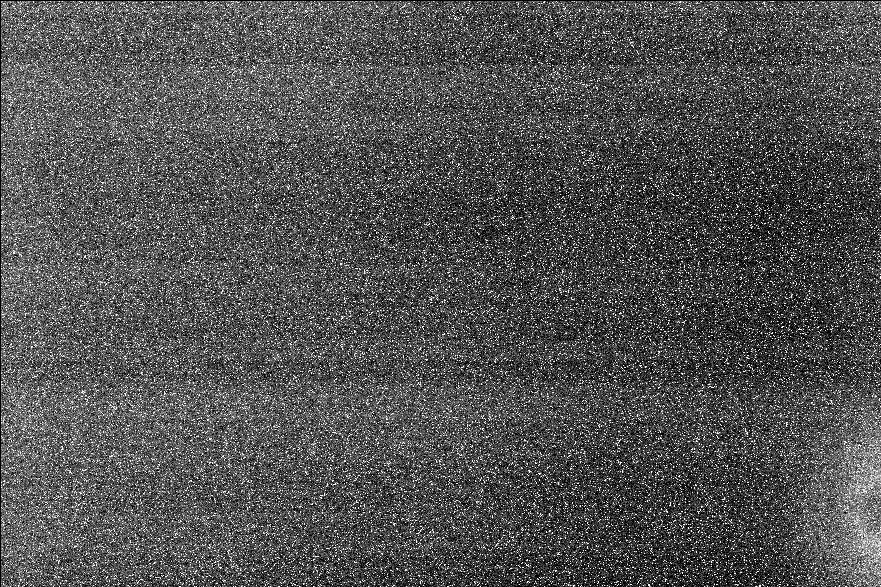
Fig.6 - Amplifier glow (lower right) in a 612 sec exposure of a Canon 20D.
For exposures of less than a second or so, read noise is relatively constant and thermal noise constitutes a negligible contribution to overall image noise. It will not be considered further in our discussion.
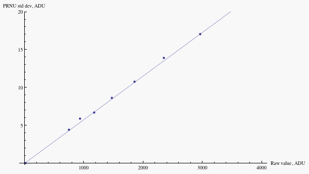
Fig.7 - Noise due to pixel response non-uniformity
of a Canon 20D at ISO 100, as a function of raw value. Mouse over to compare
to the magnitude
of combined read noise and photon shot noise. Fluctuations in the response from
pixel to pixel are about 0.6%.
PRNU "noise" grows in proportion to the exposure level -- different pixels record differing percentages of the photons incident upon them, and so the contribution to the standard deviation of raw values from PRNU rises in direct proportion to the exposure level. On the other hand, photon shot noise grows as the square root of exposure; and read noise is independent of exposure level. Thus PRNU is most important at the highest exposure levels, as one sees from the mouseover in Figure 7. For instance, PRNU is equal to combined shot and read noise at raw value of about 2500 on my 20D (roughly the top 2/3 EV of highlights) at ISO 100. At lower exposure levels, photon noise is the dominant contribution until one gets into deep shadows where read noise becomes important.

Fig. 8 - The error introduced by quantization of a noisy
signal is rather small. On the left, noise of width eight levels;
on the right,
the quantization step is increased to eight levels, but the width of the histogram
increases by less than 10%.
Noise of width 8 levels on the 0-255 scale was added to a uniform gray background; then the bit depth was truncated by squeezing the levels by a factor eight and then re-expanding by a factor eight. The left side of the image shows the image and its histogram before increasing the quantization step; on the right, the quantization step is made equal to the original width of the noise profile, and the standard deviation of the histogram rises by less than ten percent. More generally, in a typical image the roundoff error will vary from pixel to pixel, taking all values between plus and minus half the quantization step. Averaging the quantization error over a uniformly distributed set of input values will yield an average quantization error of about 0.3 of the quantization step. Thus, quantization error is negligible in digital imaging provided the noise exceeds the quantization step.